Three phase transformer connections phasor diagrams Transformer connections voltage wired Medium voltage transformer wiring diagram current transformer connection diagram
Medium Voltage Transformer Wiring Diagram - Wiring Diagram
Wiring transformer current diagram Amp meter current transformer wiring diagram Transformer connections phase three vector diagram schematic electrical groups secondary primary beginners turns
480 volt three phase transformer wiring diagram
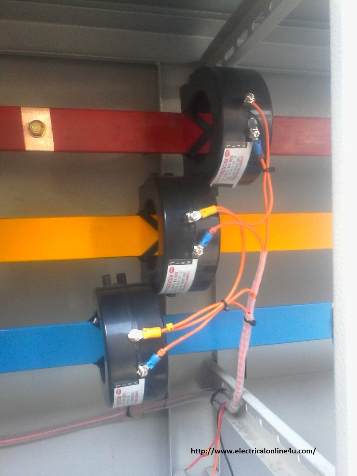
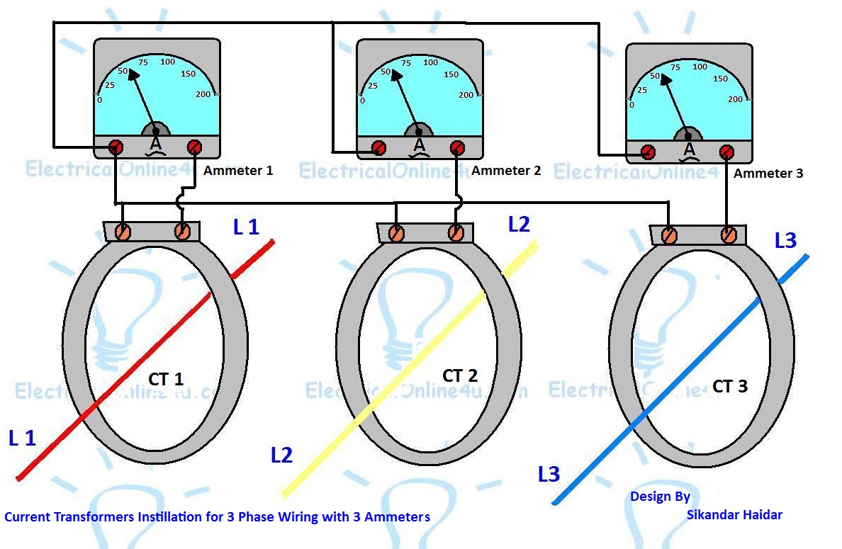
Current transformer wiring diagram phase ct meter coil three installation ammeter wire power ampere connection meters supply transformers volt digitalInstallation of current transformers Three-phase transformer connectionsTransformer wiring diagram explained.
Current transformer (ct)Three phase transformer connections and basics Three-phase transformer connections and vector groups for beginnersTransformer current diagram ct circuit principle working construction symbol operating.
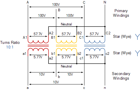
Three phase transformer connections
Transformer wiring symbols schematic diagrams connection wye 2020cadillacCurrent transformer installation for three phase power supply- ct coil Summation transformer transformers sequence phases comparing quantities relaying circuitglobeEasy understanding of 3-phase transformer connections (delta–delta, wye.
3 phase transformer wiring diagramWhat is summation current transformer? definition & types Transformer vector diagramHow to wire a transformer diagram.

Transformer current basics
Digital ammeter wiring with current transformerTransformer delta diagram wiring wye wire connection phase connections banks power circuit neutral current 12v figure Current transformerTransformer phase electronics impedance trasformatore winding starter connected kva collegamenti.
Current transformer basics and the current transformerProper installation of current transformers Current transformer installation for three phase power supply- ct coilCurrent wiring ct diagram transformers installation metering connection schematic janitza umg el grounding fig example.

Current transformer wiring installation ct diagram phase coil power three supply meter connect electrical coils amp so
Transformers installation orientationEasy understanding of 3-phase transformer connections (delta–delta, wye Transformer phase diagram wye three delta phasor wiring connections diagrams connection find electrical fig gif android closeTransformer wiring diagram explained : how to wire 3 phase.
[diagram] single phase transformer connections diagram .


![[DIAGRAM] Single Phase Transformer Connections Diagram - MYDIAGRAM.ONLINE](https://i2.wp.com/electrical-engineering-portal.com/wp-content/uploads/2017/07/wye-delta-transformer-connections.png)